Dynamic load calculator for the study of radiant system design and operation.
Status: Completed
Funding Sources: California EPIC Program CBE partners Price Industries in-kind support
Project Objective
There are two key objectives of the CBE Rad Tool project: First, to facilitate steady-state calculations which currently represent a standard design practice. Second, to enable dynamic simulations that account for transient heat gains effects on both surface heat flux and hydronic plant cooling rates.
Project Results
CBE Rad Tool was released as a beta version in 2018. This tool facilitates existing steady-state load calculations for high thermal mass radiant systems, and adds transient load analysis to improve design and operation effectiveness. The tool is simple to use and web-based and allows designers to explore ways to reduce energy consumption, cooling plant size, and electricity costs.
Significance to Industry
Engineers use load calculation tools to size HVAC systems required to maintain comfortable indoor environments. HVAC designers typically perform these calculations under steady-state conditions with constant zone dry-bulb setpoint temperatures. However, these assumptions are not appropriate for the design of high thermal mass radiant systems in which the rate of temperature change of the ‘active’ surface is slow, limiting the real-time control of the space cooling rate of the system and by extension, the indoor thermal environment.
Detailed dynamic simulation tools improve our ability to properly calculate the space cooling rate and the size of the hydronic plant for high thermal mass radiant systems. However, detailed simulation tools are complicated, time-consuming, and will rarely be used during the early design phase of a project. The CBE Rad Tool is an interactive, web-based design tool for high thermal mass radiant systems that allows users to input values for typical design and control parameters, such as time and duration of operation for the cooling plant.
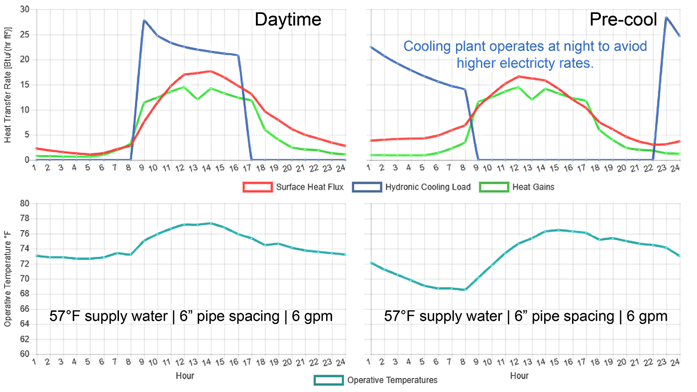
CBE Rad Tool is especially unique because it allows designers to consider the impacts of innovative control strategies such as nighttime cooling plant operation or other strategies to reduce high electricity time-of-use charges. Designers may also consider the reduction in the required hydronic plant cooling capacity by extending the hours of operation, potentially also saving on capital costs. The tool outputs are time series values for surface heat flux, hydronic system cooling rate, and indoor operative temperature.
Research Approach
CBE Rad Tool uses two load calculation methods for the early design of high thermal mass radiant systems. In the first method, it uses steady-state conditions to estimate the heating and cooling performance of high thermal mass radiant systems. The tool calculates a characteristic curve that shows the relationship between the surface heat flux and fluid differential temperature in the system. The characteristic curve, or the equivalent heat transmission coefficient, depends on the radiant system construction type, supply fluid temperature, indoor zone temperature, among other design parameters. The tool then uses the total surface heat flux capacity and other radiant system parameters to calculate the fluid velocity and pressure drop in the slab, and the number of loops needed in the user defined zone. These steady-calculation methods are based on international standards.
In the second method, CBE Rad Tool team used EnergyPlus to pre-simulate over 2.5 million different zone and radiant system design parameters on a standard ASHRAE cooling design day. Users can then select input parameters from drop-down menus to retrieve pre-simulated cases. The system design parameters include the selection of system operation start time and duration. The inclusion of time parameters is important because the slab surface temperature change rate is low after a control input (change in supply water flow rate or temperature) affecting real-time control of surface heat flux of the system. CBE Rad Tool displays 24-hour profiles for analysis by the user.
The pre-simulated cases represent one thermal zone with a thermally activated building system in a perimeter middle floor zone of a large office building. This is accomplished by thermally interconnecting the floor and ceiling surfaces of the single thermal zone. The thermal zone only has one exterior surface and the rest are defined with adiabatic surface conditions. The exterior surface construction is complaint with Title 24-2013. It also includes a window that is also complaint with Title 24-2013 where users can select from different window-to-wall ratios. The zone’s orientation and heat gains, and radiant system’s water flow rate and temperature also have various factors in which users can select from. All input parameters where based on sensitivity analysis for a cooling design day.
Publications and Reports
Raftery, P., C. Duarte, S. Schiavon, and F. Bauman. 2017. A new control strategy for high thermal mass radiant systems. Proceedings of Building Simulation 2017 Conference. August. http://escholarship.org/uc/item/5tz4n92b
Presentations
C. Duarte, S. Yang, P. Raftery, S. Schiavon and F. Bauman, 2019.
Development and Demonstration of an Interactive Web-based Design Tool for High-Thermal Mass Radiant Cooling Systems