
Berkeley Decarb Tool
An online tool for early-phase building HVAC decarbonization.
HVAC
HVAC
An online tool for early-phase building HVAC decarbonization.
HVAC
HVAC

Achieving deep energy reductions using integrated design solutions with advanced low-energy and high indoor environmental quality building technologies.
HVAC
Peer-reviewed technical guidance for design teams and building operators.
HVAC
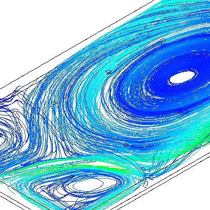
Development of the first tool to provide accurate whole-building modeling of the energy performance of underfloor systems.
HVAC

The study and documentation of current industry practices, design trends, success stories, and lessons learned.
HVAC

Occupant surveys are an invaluable source of information regarding occupant satisfaction and workplace effectiveness.
HVAC
Providing simplified design tools for optimization of underfloor systems.
HVAC
HVAC
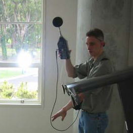
Verifying acoustical performance of as-built partitions and acoustical construction.
HVAC
IEQ